VLAN Trunking Protocol
VLAN Trunking Protocol is used by Cisco switches to exchange VLAN information. In VTP, synchronization of VLAN information, such as VLAN ID or VLAN name can be done with switches inside the same VTP domain.
VTP domain is a group of trunked switches with the matching VTP settings such as domain name, password and VTP version. All switches present in the same VTP domain share their VLAN information with each other.
For better understanding of VTP, consider an example network with 50 switches. Without VTP, if we want to create a VLAN on each switch, you should manually enter VLAN configuration commands on every switch. But when comes to VTP, it enables you to create the VLAN only on a single switch. That Particular switch can propagate information about the VLAN to every other switch on the network and cause other switches to create it. Similarly, if we delete a VLAN, the change is automatically transmitted to every other switch inside the same domain.
VTP share VLANs information through VTP messages. VTP messages can only be transmitted through the trunk connections. So we need to establish trunk connection between switches. VTP messages are transmitted as layer 2 multicast frames.VTP does not publicize information about which switch ports are assigned to which VLAN.
Related – VDC vs VLAN
VLAN Trunking Protocol VERSIONS:
There are three versions in VTP
- Version 1
- Version 2
- Version 3
Among the three, Version 3 is most popular and has following features –
- Enhanced authentication
- Support for extended VLANs (1006 to 4094). It also support for private VLAN
- VTP mode off that disables VTP
- Backward compatibility with VTP V1 and V2
VLAN Trunking Protocol (VTP) MODES:
VTP can be configured in four different modes
- VTP Server Mode
- VTP Client Mode
- VTP Transparent Mode
- VTP Off Mode
VTP Server Mode:
- VLANs can be created, modified, and deleted in VTP server and configuration parameters, such as VTP version and VTP pruning can also be specified for the entire VTP domain.
- VTP servers publicize their VLAN configuration to other switches in the same VTP domain and synchronize their VLAN configuration with other switches based on advertisements received over trunk links.
- VTP server is the default mode.
- Saves Configuration in NVRAM
VTP Client Mode:
- VTP clients are similar to the VTP servers. The only difference is that we cannot create, change, or delete VLANs on a VTP client.
- Doesn’t save Configuration in NVRAM
VTP Transparent Mode:
- VTP transparent switches do not take part in VTP.
- VTP transparent switch does not publicize its VLAN configuration and does not synchronize its VLAN configuration based on received advertisements, but transparent switches forward VTP advertisements that they receive from trunk ports.
- In addition to supporting private VLANs in client and server modes, VTP version 3 also supports creating extended-range VLANs in client or server mode
VTP Off Mode:
It is similar to the transparent mode. The only difference is that a switch using this mode will not forward received VTP updates. It is supported only in VTP Version3.
Configuration Revision Number:
- Vlan Trunking Protocol switches use a pointer called the VTP configuration Revision Number to notify the most recent information.
- Configuration revision number is zero (0) when VTP advertisement process starts.
- When modification is made on a VTP server, the revision number is incremented by one before the advertisement is sent.
How to add a new switch into the existing VLAN Trunking Protocol Domain
- While adding a switch to an existing VTP domain, make sure that the switch VTP Revision number is 0 before adding it to a network.
- Reform the switches VTP mode to transparent and then change the mode back to server.
- VTP domain name should be changed to a fake name (a nonexistent vtp domain), and then change the VTP domain back to original name.
- Remove the Vlan .Dat file inside the flash and reload it.
VLAN Trunking Protocol (VTP) CONFIGURATION
There are some prerequisites for VTP to transmit VLAN information between switches.
- Switches which are to be VTP configured should be with the same domain name and same version.
- There must be one server switch among the switches.
- Authentications like Password should match if applied.
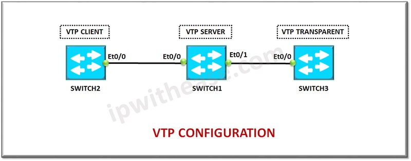
Below is a sample lab setup showcasing VTP Server, Client and transparent mode for Switch1, Switch2 and Switch3 respectively.
Configuration of VTP Server Mode in Switch 1
Switch1(config)#interface range Ethernet 0/1
Switch1(config-if-range)# switchport trunk encapsulation dot1q
Switch1(config-if-range)#switchport mode trunk
Switch1(config-if)#exit
Switch1(config)#exit
Switch1#configure t
Switch1(config)# vtp domain cisco
Switch1(config)# vtp mode server
Switch1 (config)#exit
Configuration of VTP Client Mode in Switch 2
Switch2 (config) #interface range Ethernet 0/0
Switch2(config-if-range)# switchport trunk encapsulation dot1q
Switch2(config-if-range)#switchport mode trunk
Switch2(config-if)#exit
Switch1(config)#exit
Switch2#configure t
Switch2(config)# vtp domain cisco
Switch2(config)# vtp mode client
Switch2(config)#exit
Configuration of VTP Transparent Mode in Switch 3
Switch3(config)#interface range Ethernet 0/0
Switch3(config-if-range)# switchport trunk encapsulation dot1q
Switch3(config-if-range)#switchport mode trunk
Switch3(config-if)#exit
Switch3(config)#exit
Switch3#configure t
Switch3(config)# vtp domain cisco
Switch3(config)# vtp mode transparent
Switch3(config)#exit
Below is the VTP mode after configuring the mode as server in Switch1.
VTP Version capable : 1 to 3 VTP version running : 1 VTP Domain Name : cisco VTP Pruning Mode : Disabled VTP Traps Generation : Disabled Device ID : aabb.cc80.1000 Configuration last modified by 0.0.0.0 at 0-0-00 00:00:00 Local updater ID is 0.0.0.0 (no valid interface found) Feature VLAN: —————– VTP Operating Mode : Server Maximum VLANs supported locally : 1005 Number of existing VLANs : 5 Configuration Revision : 0 MD5 digest : 0x57 0x30 0x6D 0x7A 0x76 0x12 0x7B 0x40 0x00 0x7F 0xD1 0x16 0x72 0xC1 0x1C 0x8F *** MD5 digest checksum mismatch on trunk: Et0/0 *** *** MD5 digest checksum mismatch on trunk: Et0/1 ** VTP Version capable : 1 to 3 VTP version running : 1 VTP Domain Name : cisco VTP Pruning Mode : Disabled VTP Traps Generation : Disabled Device ID : aabb.cc80.2000 Configuration last modified by 0.0.0.0 at 0-0-00 00:00:00 Feature VLAN: —————– VTP Operating Mode : Client Maximum VLANs supported locally : 1005 Number of existing VLANs : 5 Configuration Revision : 0 MD5 digest : 0x57 0xCD 0x40 0x65 0x63 0x59 0x47 0xBD 0x56 0x9D 0x4A 0x3E 0xA5 0x69 0x35 0xBC *** MD5 digest checksum mismatch on trunk: Et0/0 *** VTP Version capable : 1 to 3 VTP version running : 1 VTP Domain Name : cisco VTP Pruning Mode : Disabled VTP Traps Generation : Disabled Device ID : aabb.cc80.3000 Configuration last modified by 0.0.0.0 at 0-0-00 00:00:00 Feature VLAN: —————– VTP Operating Mode : Transparent Maximum VLANs supported locally : 1005 Number of existing VLANs : 5 Configuration Revision : 0 MD5 digest : 0x57 0xCD 0x40 0x65 0x63 0x59 0x47 0xBD 0x56 0x9D 0x4A 0x3E 0xA5 0x69 0x35 0xBC *** MD5 digest checksum mismatch on trunk: Et0/0 *** Configuration of switch 1 Switch1#configure t Switch1(config)#vlan 10 Switch1(config-vlan)#exit Switch1(config)# vlan 20 Switch1(config-vlan)#exit Switch1(config)#exit VLAN Name Status Ports ——————————————————————————————————————– 1 default active Et0/2, Et0/3 10 VLAN0010 active 20 VLAN0020 active 1002 fddi-default act/ unsup 1003 token-ring-default act/ unsup 1004 fddinet-default act/ unsup 1005 Trnet-default act/ unsup VLAN Name Status Ports —————————————————————————————————————————– 1 default active Et0/1,Et0/2, Et0/3 10 VLAN0010 active 20 VLAN0020 active 1002 Fddi-default act/unsup 1003 token-ring-default act/unsup 1004 Fddinet-default act/unsup 1005 trnet-default act/unsup Note: As per the output, VLAN 10 & VLAN 20 are created in switch 1. Henceforth, VLAN 10 & VLAN 20 are also created in Switch2 by automatically (by VTP) because Switch 1 is VTP server, Switch 2 is VTP Client. VLAN Name Status Ports —————————————————————————————————————————- 1 default active Et0/1, Et0/2, Et0/3 1002 fddi-default act/unsup 1003 token-ring-default act/unsup 1004 fddinet-default act/unsup 1005 trnet-default act/unsup Note: As per the output, no VLANs are created automatically in switch 3, because Switch 3 is VTP transparent. Related – VTP Interview Q&ABelow is the information of VTP mode after configuring the mode as client in Switch2.
Below is the information of VTP mode after configuring the mode as transparent in Switch3.
VLAN 10 & VLAN 20 configuration on switch 1.
Showing the information about VLANs in Switch 1 use “show vlan brief” command.
Showing the information about VLANs in Switch 2.
Information about VLAN 10 & VLAN 20 in Switch 3.