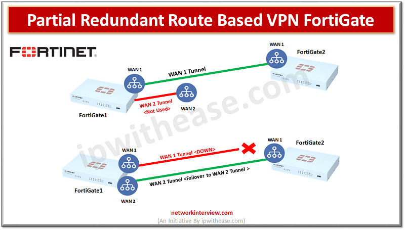
Partial Redundant Route Based VPN FortiGate
Objectives
- FortiGate1 has two WAN links and FortiGate2 has single WAN link
- Create site-to-site route based VPN with Redundant Connection
- Configure Dead-Peer-Detection failover
- Configure Link-Health
Partial Redundancy is where we don’t have primary and secondary WAN connections on both peer1 and peer2 sides so usually it can be headquarters that has multiple connections and there might be a remote office in which the setup has only one WAN link. To communicate in such a kind of network setup we need to create a redundant VPN. Redundant and partially redundant VPN uses Route Based VPN.
Create site-to-site route based VPN with Redundant Connection
In this example we have taken a FortiGate1 device with 2 WAN links and a FortiGate2 device with a single WAN. Hence redundancy will be established at FortiGate1 side because it has 2 different WAN links. (refer diagram shown above)
>>Configure Site-to-Site VPN in FortiGate1 (HQ) for WAN1 and WAN2-Route Based
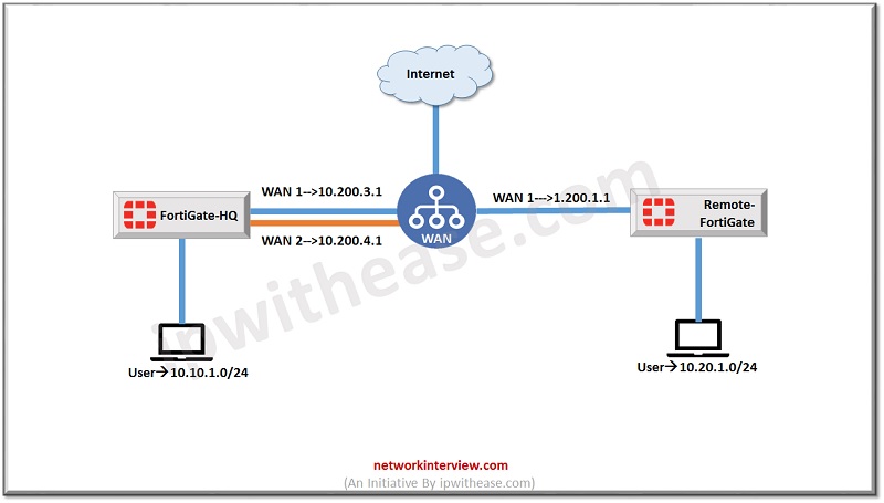
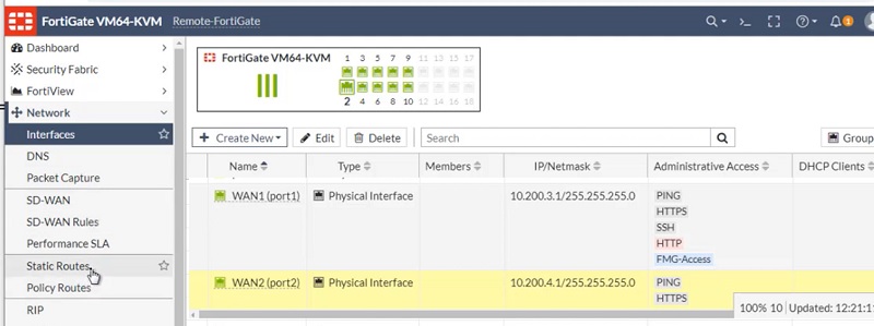
Check WAN 1 and WAN2 interfaces and its IP addresses
WAN 1 -> 10.200.3.1/24
WAN 2 -> 10.200.4.1/24
Check LAN IP address -> 10.10.1.0/24
Configure Phase-1 for WAN 1
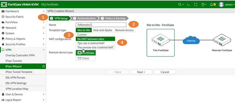
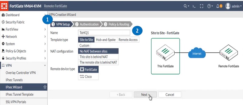
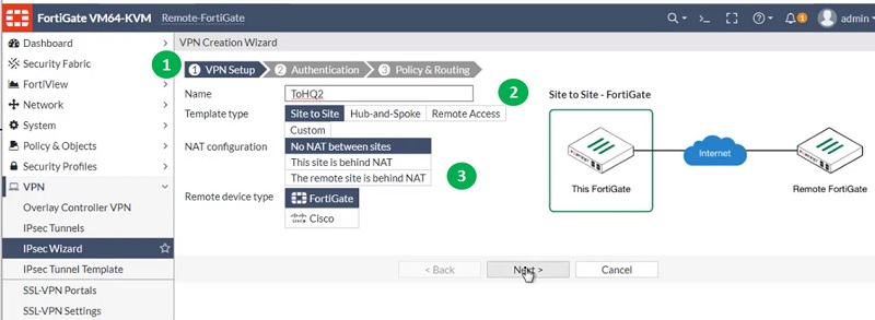
- Go to IPSec Wizard and select VPN Setup
- Name VPN profile ToRemote1
- Select Template Type -> Site to Site
- NAT configuration is NO NAT

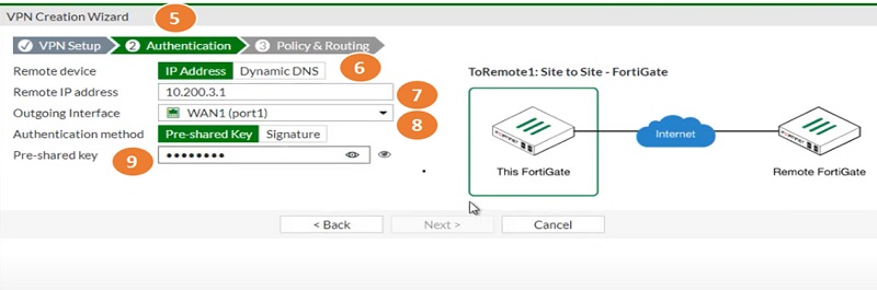
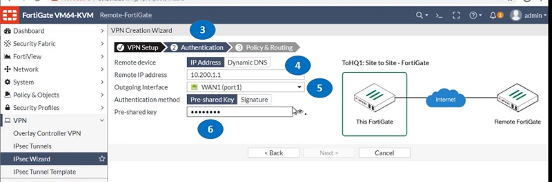
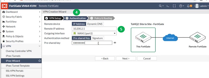
- Select next tab Authentication
- Select IP address
- Select Remote IP Address of WAN1
- Select Outgoing port WAN1
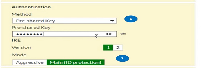
- Enter Pre-shared Key which must be identical with peer site configuration

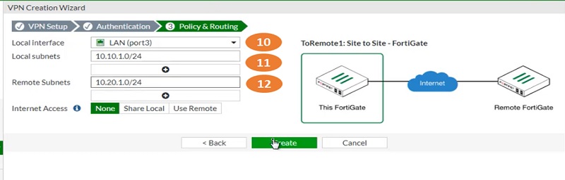
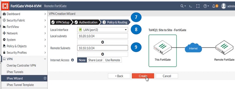
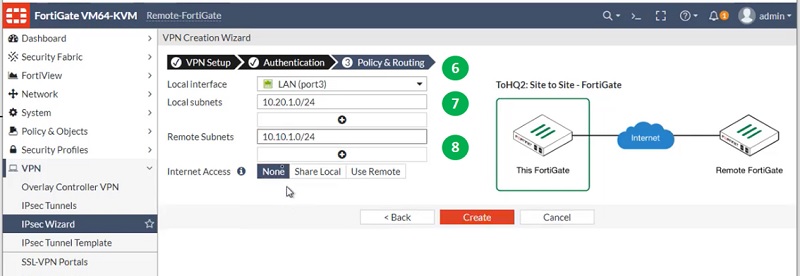
- Select next tab Policy & Routing and add LAN interface port
- Add Local subnets -> 10.10.1.0/24
- Add remote site subnets-> 10.20.1.0/24
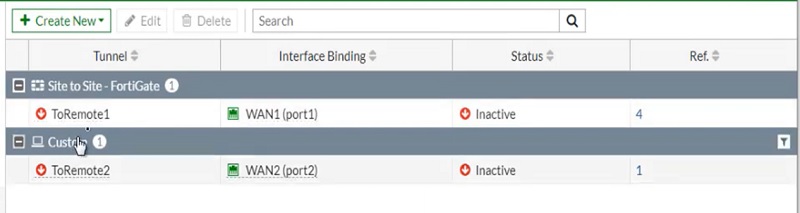
- Now Tunnel has been for WAN1 interface

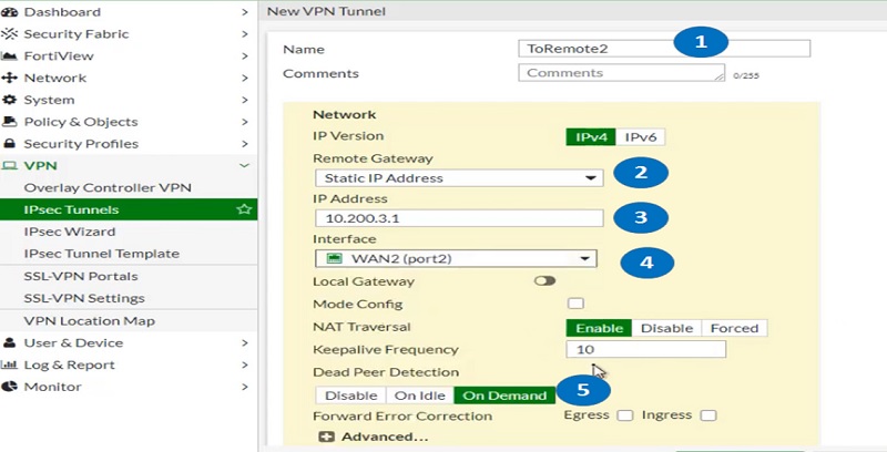
Configure Tunnel for WAN 2
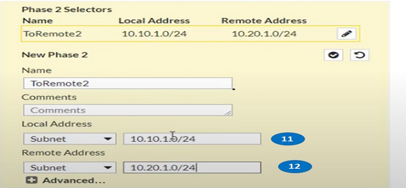
- Add name for Phase 2 tunnel parameters
- Add Remote Gateway outgoing IP address
- Add WAN1 interface IP address
- Select WAN 2 Port for outgoing interface
- Enable Dead Peer detection

- Add Authentication for phase 2 IDs. Add pre-shared keys.
- Add Main Mode
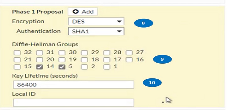
- Add encryption and Authentication methods
- Enable Diffie-Hellman values
- Add key-lifetime values.

- Add local address -> 10.10.1.0/24
- Add remote address -> 10.20.1.0/24

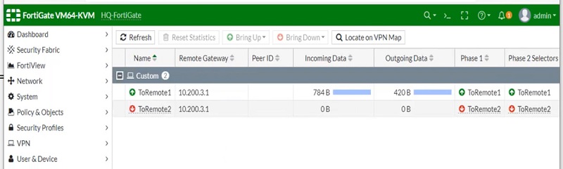
Both tunnels WAN1 and WAN2 have been created.
Configure Routes for WAN 1 and WAN 2 Tunnels
Go to tab Network > Static Routes.
1. Choose Create New, enter below entries and select OK:
Destination IP/Mask 0.0.0.0/0.0.0.0
Device WAN1
Gateway 10.200.3.1
Distance (Advanced) 10 -> Lower Values
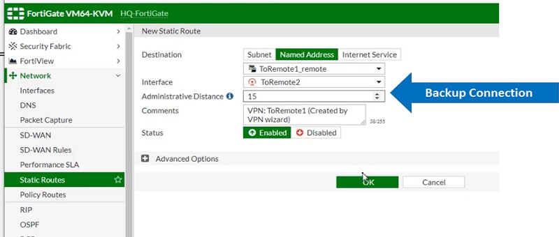
Add another route for WAN2, now go to Network > Static Routes.
2. Choose Create New, enter below entries select OK:
Destination IP/Mask 0.0.0.0/0.0.0.0
Device WAN2
Gateway 10.200.4.1
Distance (Advanced) 15 -> Higher Value as it is secondary route
Create Security Policy for WAN 1 and WAN 2
>Create Security Policy for Wan 1 and WAN 2 traffic to communicate with Remote site
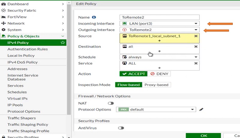
1. Go toPolicy & Objects > IPv4 Policy and select Create New-Policy.
2. Add below information in policy parameters:
Incoming Interface LAN
Outgoing Interface ToRemote2
Source Address LAN Subnets (Specific subnets which you want to allow)
Destination Address All
Schedule Always
Service Any
Action ACCEPT
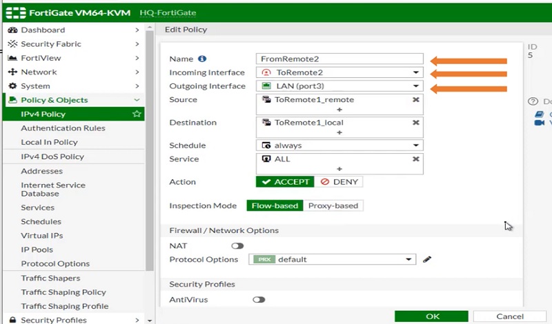
Create Security Policy From Remote site to FortiGate-HQ site
3. Enter the following information, and select OK:
Incoming Interface ToRemote2
Outgoing Interface LAN
Source Address required subnets for remote sites
Destination Address Local Subnets
Schedule Always
Service Any
Action ACCEPT
Configure Tunnel on Remote Peer FortiGate for WAN1
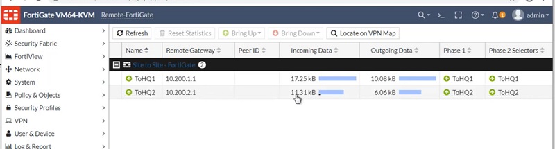
Configure tunnel on Remote Peer FortiGate for WAN1. Configure FortiGate in a similar way which we have configured FortiGate1-HQ.
Two tunnels will be created on Remote-FortiGate, first for WAN1 link and second tunnel for WAN2 link. However Remote-FortiGate has a single link at their end.
- Select VPN Wizard and go to VPN Setup
- Name VPN Tunnel Name TOHQ1

- Select Authentication Tab and add values to the mentioned parameters
- Remote device IP address
- Add IP address of Remote-FortiGate
- Select Outgoing Interface WAN1 and add a pre-shared key which must be identical with FortiGate1-HQ’s pre-shared key.
- Move to Policy & Routing tab, add parameters in secondary route
- Add local subnets 10.20.1.0/24
- Add remote subnets 10.10.1.0/24 and add these routes along with the tunnel and create the tunnel

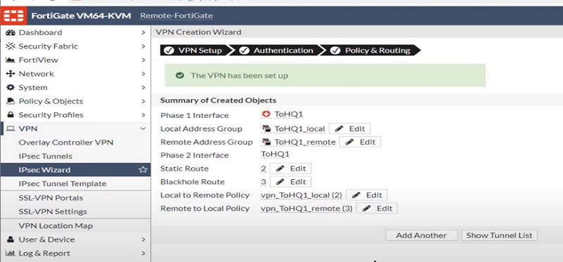
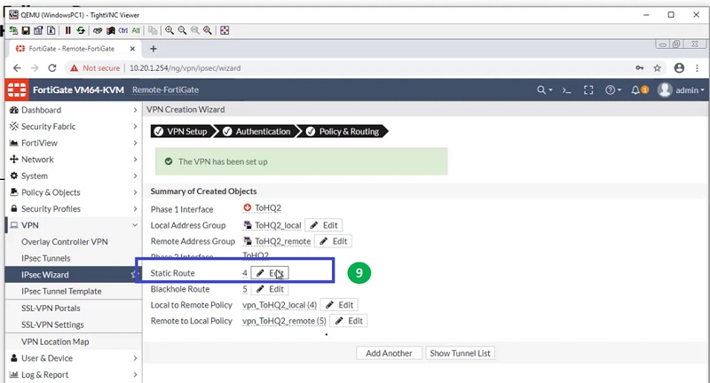
Tunnel is ready on the Remote-FortiGate firewall for Link WAN1. See below image to check added parameters.
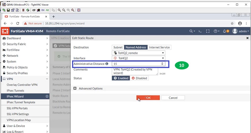
Create Tunnel from Remote FortiGate to WAN 2
Now create another tunnel for FortiGate HQ with lower administrative distance. Here, we will select administrative distance 10 to prioritise the route.
Follow step 1 to step 10 to get the tunnel created on Remote FortiGate Firewall.
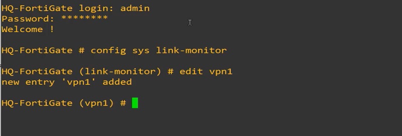
Configure Link-Health Monitor
>>Configure Link-Monitor on FortiGate-HQ
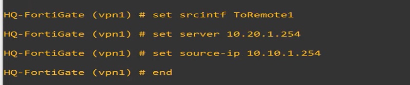
Here, probing is done by ToRemote1 interface.
We can also check the status of probing IP address by using below command
diagnose sys link-monitor status
>>Link-health monitor on Remote-FortiGate Firewall
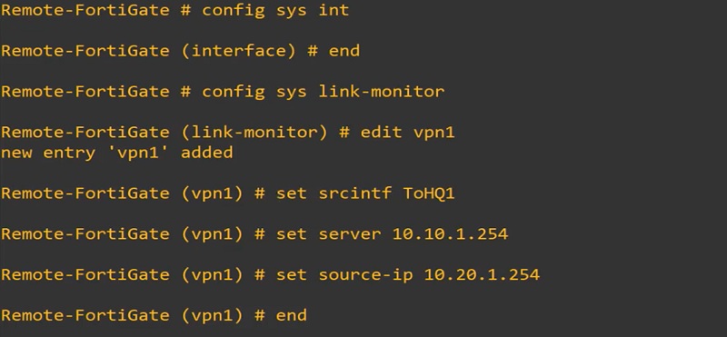
These health monitors can probe the destination by sending signals to the WAN1 and WAN2 or vice-versa. You can configure Link-Monitor through CLI only.
Continue Reading:
FortiGate NAT Policy: Types & Configuration
Routing Configuration in FortiGate Firewall: Static, Dynamic & Policy Based