TORA – Ad hoc Wireless Network
Temporally Ordered Routing Algorithm is abbreviated as TORA which is a source that is initiated on demand routing protocol. The invention of this protocol was done in 1997 by Vincent Park and M. Scott Corson who belongs from the university of Maryland. Its main purpose is for the wireless ad hoc network.
TORA is a highly efficient, adaptive, scalable and loop-free routing protocol that is based on algorithm of link reversal. Objective of the TORA is to limit the propagation of message in the computing environment that is highly dynamic in mobility. In other words, it is planned for the reduction of communication overhead by the adaptation of changes in local topological with regards to ad hoc network. One more feature of TORA routing protocol is the localization of data to a small area near the existence of a changes in topological that is because of the breakage of route. Therefore, every node of the network requires its topological information and local routing about the adjacent nodes.
It has the ability to exhibits multipath routing that is it support multiple routes for transmitting the data packet between the source to the destination of mobile ad hoc network. One of the main advantages of TORA is that it is operated smoothly in an environment that has high dynamic mobility.
The working of TORA is done in three phases – Creation of route, Maintenance of route and Erasing of route.
Phase 1 – Route creation: Creation of route from source to destination.
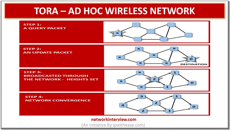
The process involves the establishment of sequence of links from the source to the destination. The model shows the algorithm that generates a Directed Acyclic Graph which is based on the parameter known as height. It measures the distance of the node from the responding node to destination node. A node with lesser height is considered downstream and one with higher height is considered as upstream.
Phase 2 – Route maintenance: Maintenance of the route.
This refers to the responding the changes in topological in the network which is done in manner that there is re-establishment of destination route in a finite time. The process is invoked by the route creation when there is no occurrence of downstream. The very first steps involve the checking of the link failures.
Phase 3 – Route erasure: Erasing of the route when the route is no longer valid.
All the invalid routes should be removed from the network if ant partition is detected in the network. This process is done by the undirecting the directed routes.
TORA endeavours to manufacture a different directed non-cyclic diagram (DAG) by every node to each destination. At the point when a course to a specific destination is required, the source node communicates a QUERY bundle containing the location of the destination. The course question spreads through the system till it comes to either the destination or a transitional node containing the course to the destination.
Quintuple metric is required by the TORA that comprises of:
- A reflection indicator bit.
- Unique ID of the node.
- Logical time of link failure.
- A propagation ordering parameter.
- Unique ID of the node that defines the new reference level.
Architecture of a node
The basic blocks the includes in the architecture of node is router processor, memory structures, control signals and buffers for temporary storage which helps in coordination for different processes.
Router processor: It is the main component that reads every bit of the packet that is received and ensure the series as per TORA algorithm.
Memory structure: It comprise of two types- neighbour status memory that is utilized to store the details about height. Another one is link status memory that store the details regarding the linkage of adjacent neighbour.
Control signals: Read and write are the two-control signal used in this configuration. The read signal indicates the input buffer while the write signal gives the signal for the transferring the packet to the network.
Buffers: There are two buffers for temporary storage. One is input buffer that is build according to the maximum size od packets that can be received. Another one is output buffer which comprises of processed packets.
Related – Wireless Interview Q&A


