Structured Cabling Explained: Standards, Subsystems, and Where Installs Go Wrong
Structured cabling is a standards-based approach to building a network’s physical layer, where the cabling is designed as one documented system of defined subsystems rather than as a collection of point-to-point runs added when a port was needed. The issue is that cabling often outlives the equipment attached to it. Switches get replaced every five to seven years and access points more often than that, while a properly designed cabling plant (the complete physical infrastructure of copper wires, fiber optic cables, connectors, and hardware that transmits signals between communication devices) is expected to serve for fifteen or twenty.
This is why there are standards that govern the pathways, the terminations and the documentation as tightly as they govern the cable itself in a structured cabling system.
Key takeaways
- Structured cabling is defined by subsystems and standards, not by cable type; Cat6A and fiber are choices made inside the design, not the design itself.
- TIA-568 and ISO/IEC 11801 are the two standards families you will encounter, and they cover topology, distances, performance classes and administration.
- The 90-metre horizontal limit is a design constraint, not a suggestion, and it drives where telecom rooms have to sit.
- A wiremap test proves the pins are connected; certification proves the channel meets its performance class, and only one of those is evidence.
- Most failures traced back to the physical layer come from pathway and installation practice rather than from the cable specification.
What is Structured Cabling?
Before the standards existed, network wiring grew the way office furniture does. Somebody needed a connection, someone ran a cable to it, and after a decade the ceiling held hundreds of undocumented runs that nobody dared touch. Moves and changes became expensive because every one of them started with tracing.
The structured approach replaces that with a hierarchy. Cable runs from an outlet at the desk back to a patch panel in a telecom room; the telecom rooms connect back to a main equipment room over a backbone, and everything terminates on documented hardware in a documented position. When a user moves, you move a patch cord instead of running cable.
That hierarchy is the reason the model scales. Any device that uses Ethernet can attach anywhere on the plant, and the plant does not need to know or care what that device is, which is what lets you swap a generation of switches without touching a single permanent link.
The Six Subsystems, and Which ones get Skipped
The standards divide the plant into subsystems so that each one can be designed, tested and documented separately.
1. Entrance facility
This is where service from outside the building lands, including the demarcation point, which is the boundary where the provider’s responsibility ends, and yours begins, plus the protection hardware. It is the subsystem most likely to be inherited rather than designed, and the one most likely to be undersized when a building’s tenancy changes.
2. Equipment room
This is the central space housing the core equipment and the main cross-connect, which is the central patching frame where the building’s backbone cables all terminate and can be reconfigured. Its constraints are environmental as much as anything, since cooling and power capacity here set the ceiling on what the building can support.
3. Backbone cabling
These are the runs between the entrance facility, the equipment room and each telecom room. This is where fiber usually appears, and where undersizing hurts the most, because pulling additional backbone later costs far more than installing spare strands at the outset.
4. Telecommunications room
This is the floor-serving space that holds that floor’s patching frame. Its position determines whether the horizontal runs can meet their distance limit, which makes it a floor-plan decision rather than a networking one.
5. Horizontal cabling
These are the runs from the telecom room out to each work area outlet, limited to 90 meters of permanent link with a further 10 meters allowed for patch cords at both ends. This subsystem is the bulk of the cable in any building and the one that is hardest to change afterwards.
6. Work area
This subsystem covers the outlet, the faceplate and the cord to the device, and it is trivial to change, which is exactly the point of pushing all the permanence back into the other five.
Subsystems that often go overlooked
The subsystems most often skipped are the least visible ones. Cable pathways get treated as an afterthought, so there is nowhere safe to route the next cable, and administration, meaning the labelling and record-keeping, gets skipped entirely, so nobody can identify a run without tracing it by hand.
That is how a building ends up with an excellent cable specification and an installation nobody can work on. Treating structured cabling as a designed and documented system from the outset, rather than as a series of cable pulls, is what keeps all six subsystems usable later.
The Standards that Govern the Install
Two standards families cover this work, and they overlap heavily.
The ANSI/TIA-568 series is the North American reference, published by the Telecommunications Industry Association, an ANSI-accredited standards-developing organization. It defines the layout, the distance limits, the performance classes for copper and fiber, and the requirements for testing and administration. ISO/IEC 11801 is the international equivalent and uses class designations rather than category numbers, so Class EA corresponds broadly to Category 6A.
Alongside them sits the design and installation practice published by BICSI, whose manuals cover how the work should actually be carried out rather than what the finished channel must measure. Standards tell you the target; the practice documents tell you how installers reach it repeatably.
The distance limits, bend radii and pull tensions in these documents are the constraints that determine whether a design is buildable, and a specification written without them tends to fail at the point where cable meets building.
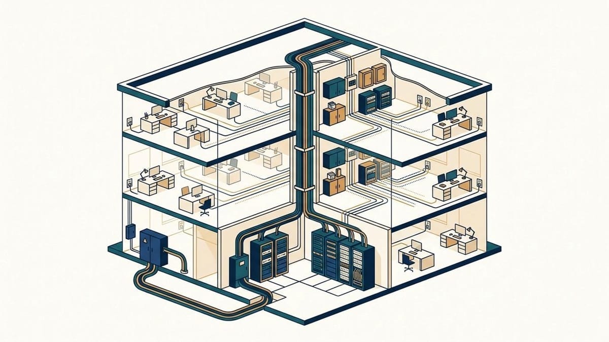
The subsystem hierarchy: service entrance and equipment room at ground level, a backbone riser between floors, a telecommunications room per floor, and horizontal runs out to each work area outlet.
Copper or Fiber in the Backbone
The horizontal is copper in nearly every commercial building, because it carries power alongside data and the work area needs that. The interesting decision is the backbone, where the trade-offs are genuinely open.
Copper backbone is limited by distance and by the fact that every meter of it is a shared collision with electrical noise and with the building’s grounding scheme. Fiber removes both problems, carries far more capacity than the current generation of switches will ask of it, and is immune to the electromagnetic interference that makes long copper runs unpredictable in industrial and healthcare settings.
The argument for fiber is usually made on capacity, but the stronger argument is lifespan. A backbone is the hardest part of the plant to replace, so the sensible design puts the longest-lived medium where replacement is most disruptive, and accepts a higher cost per meter on the runs you least want to touch again.
Where copper still earns its place is in short backbone runs inside a single building, particularly where the budget is genuinely constrained, and the distances sit comfortably inside the limits. That is a real engineering trade-off rather than a compromise, provided somebody has actually checked the distances.
Certification Testing: Why a Wiremap check is not proof
This is the step that separates an installation you can rely on from one that merely costs a lot, and it’s constantly misunderstood.
A continuity or wiremap tester confirms that the eight copper conductors inside a standard Ethernet cable reach the right pins at the far end, with no shorts, splits or reversals. What it does not tell you is whether the channel will actually carry the traffic its category promises.
Certification testing uses different equipment and produces a different kind of result. A certifier sweeps the link across its full frequency range and measures insertion loss, which is how much signal strength is lost between the two ends, along with near-end and far-end crosstalk, return loss, propagation delay and delay skew, then compares each result against the limits for the performance class being claimed. Field certifiers from Fluke Networks are the common standard for testing here, and the output is a per-link report with a pass or fail against a named standard.
Ask for those reports before signing off on a handover. A cabling plant delivered without certification results has not been proven to meet any category at all, and the moment a link starts dropping under load, nobody can say whether it was ever compliant or whether something changed. Certification is also what makes a manufacturer’s system warranty enforceable.
Where installs Go Wrong
Almost none of the physical-layer faults worth writing about come from the cable being the wrong category. They come from what happened to it during installation.
- Bundle derating is the constraint that catches most designs. Copper cable carrying Power over Ethernet (PoE) dissipates heat, and cables bundled tightly together heat each other. The IEEE 802.3bt standard raised the available power budget considerably, which made this worse rather than better, because larger bundles now carry more current than the pathway was designed around. Insertion loss rises with temperature, so a bundle that passed certification in an empty building can drift out of specification once the plant is loaded.
- Bend radius violations are permanent. Every cable has a minimum bend radius, and pulling a run around a tight corner or cinching a tie wrap too hard permanently deforms the internal pair geometry, meaning the precise twist and spacing of the wire pairs that give the cable its performance. The link often still passes a wiremap and fails certification, which is precisely why the wiremap isn’t sufficient.
- Pathway fill decides what year eight looks like. Overfilled conduit and tray make future work impossible and increase the pull tension needed on the next cable, which damages the cables already in place. Fill ratios exist so that the installation can still be added to in year eight.
- Untested moves and changes erode the record. An installation certified at handover slowly diverges from its documentation as links are re-terminated by whoever was available. Without re-testing, the certification record describes a cabling installation that no longer exists.
All of these failures are getting less forgiving, because buildings now carry far more powered cable than the pathways were originally sized for. As wireless access point counts rise to support Wi-Fi Certified 6 and its successors, every one of those access points adds another cable drawing power through the same tray, and the spare margin that used to absorb rough workmanship is no longer there. Organizations that treat cabling as a designed and certified system, rather than as a bulk purchase of cable to be pulled as cheaply as possible, tend to be the ones whose installation is still serving them a decade later.
Documentation and Labelling
The subsystem everyone skips is the one that determines what the installation costs to own over its life.
Administration under the standards means that every outlet, every cable, every patch panel port and every telecom room carries an identifier, that those identifiers appear on record drawings, and that the certification results are filed against them. Done properly, a fault becomes a lookup rather than an investigation.
Done badly, or not at all, every subsequent change starts with a technician and a tone generator, the handheld tool used to trace which cable is which, and the labour cost of that tracing over fifteen years comfortably exceeds what the documentation would have cost at handover. This is the least glamorous part of the standard and the one with the clearest return.
Getting it Right
Structured cabling rewards the decisions made before anything is pulled. Locate the wiring rooms against the distance limits rather than around whatever space was left over, size the backbone for more than the current generation of equipment will ask of it, insist on certification reports at handover, and label every run so that a future fault becomes a lookup rather than an investigation. None of that costs much at design stage, and every part of it is expensive to retrofit into a working building.
Frequently Asked Questions
Q.1 What is the difference between structured cabling and regular network cabling?
Regular cabling connects two points because something needed connecting. The structured approach designs the whole installation as documented subsystems against a standard, with a defined layout, distance limits and certification, so that it can be added to and diagnosed predictably.
Q.2 Why is horizontal cabling limited to 90 meters?
The limit comes from the signal loss budget for a 100-meter link, which allows 90 meters of permanent cable plus 10 meters of patch cords. Exceeding it means the channel can no longer be guaranteed to meet its performance class, and it drives where telecom rooms must be located.
Q.3 Is Cat6A necessary, or is Cat6 still enough?
Cat6 supports 10GBASE-T only over reduced distances and under favourable conditions, whereas Cat6A is specified for it across the full channel. For a plant expected to last fifteen years, the difference in installed cost is usually small against the cost of revisiting the decision.
Q.4 How often should a cabling plant be re-certified?
There is no fixed interval, but re-certification is warranted after any significant moves, adds or changes, after work that disturbed existing pathways, and before relying on the plant to carry a faster generation of equipment than it was originally tested for.
Q.5 Does structured cabling still matter when most devices are wireless?
It matters more than it did when most devices were wired. Every access point is a wired device with a power budget, so heavier wireless use increases the number of certified, powered links a building needs rather than reducing it.

You may also like
Types of Network Cables

The Best MCP SEO Tools for Automating Weekly SEO Reporting