How to Configure Route Leaking Between VRFs FortiGate CLI?
Cloud hosted workloads require customer traffic isolation and separate routing at logical level but through common hardware. Using virtual route forwarding (VRF) technique multiple routing tables can be created within the same router. VRF is used to divide routing functionality at layer 3 including routes, forwarding tables and interfaces into separate units. Packet forwarding happens between interfaces within the same VRF.
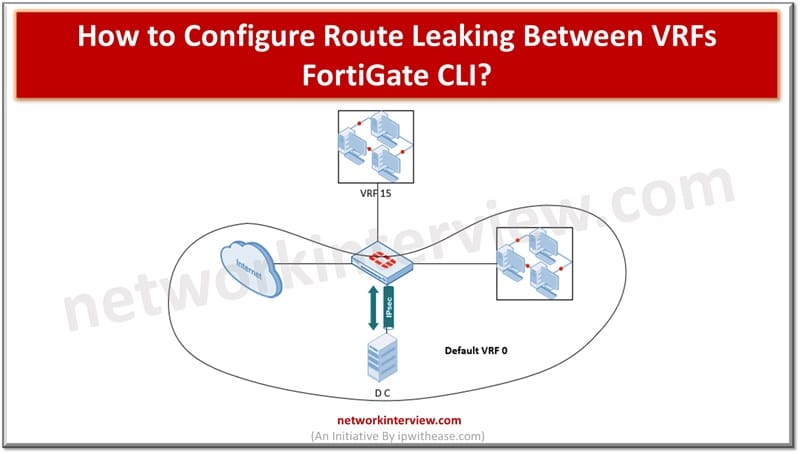
In today’s topic we will learn about how to configure route leaking between Virtual route forwarding (VRFs) FortiGate using command line interface (CLI).
What is VRFs FortiGate?
Virtual routing and forwarding (VRFs) provides virtual router functionality on physical routers. Each VRF operates in isolation and maintains its routing table, configurations and interfaces. Each VRF is a self-realm in itself unaware of the existence of others. FortiGate is like a guardian who facilitates communication among these isolated VRFs. It has the capability to manage these delicate connections. FortiGate protects the pathway between VRFs.
Configuring Route Leaking between VRFs FortiGate CLI
VRF table routes can be leaked into the Global routing table to make traffic communication possible. This scenario requires enabling and configuring a BGP neighbour.
1.Configure VDOM-Mode
Step 1:
Set the FortiGate to multi-vdom mode to create two inter-vdom links and assign them to separate VRFs. Multi-vdom creates one more virtual firewall on a single physical box. The inter-vdom created will remain in root vdom.
Configure system globa2
Set vdom-mode multi-vdom
2. Subnet Overlapping
Step 2:
By default, FortiGate on the same VDOM does not permit to configure duplicate or overlapping networks. The two inter-vdom links need to be on the same subnet.
configure vdom
edit root
config system settings
set allow-subnet-overlap enable
3. Configuring Inter-VDOM links
Step 3:
On the same subnet, configure two inter-vdom links. The links are put in their respective VRFs using set vrf (<0> to <31>).
config vdom
edit root
config system interface
edit “npu1_vlink0”
set vdom “root”
set vrf 2
set ip 10.300.0.1 255.255.255.0
set allowaccess ping ssh snmp http https
set type physical
set snmp-index 11
next
edit “npu1_vlink1”
set vdom “root”
set vrf 3
set ip 10.300.0.2 255.255.255.0
set allowaccess ping ssh snmp telnet http https
set type physical
set snmp-index 15
Put physical or virtual interfaces into respective VRFs using the below command.
config system interface
edit “wan12”
set vdom “root”
set vrf 2
set ip x.x.x.x 255.255.255.252
next
edit “vlan200”
set vdom “root”
set vrf 3
set ip 10.200.0.254 255.255.255.0
end
wan12 is put in vrf 2 so that the default route from vrf2 to vrf 3 will be leaked so that vlan 200 can have Internet access.
4. Configuration of Prefix-list
Configure the prefix-list of routes which you have intent to leak. We will be leaking here source subnet 10.200.0.0/24 of vrf3 and default route in vrf2.
config router prefix-list
edit “1”
config rule
edit 1
set prefix 0.0.0.0 0.0.0.0
unset ge
unset le
next
end
next
edit “2”
config rule
edit 1
set prefix 10.200.0.0 255.255.255.0
unset ge
unset le
next
end
next
end
5. Configuring Route-Map
Route map is used to identify subnets used in vrf leaking and matched against the prefix-list
config router route-map
edit “VRF2Routes”
config rule
edit 1
set match-ip-address “1”
unset set-ip-nexthop
unset set-ip6-nexthop
unset set-ip6-nexthop-local
unset set-originator-id
next
end
next
edit “VRF3Routes”
config rule
edit 1
set match-ip-address “2”
unset set-ip-nexthop
unset set-ip6-nexthop
unset set-ip6-nexthop-local
unset set-originator-id
next
end
next
end
6. Configuring Route Leaking
BGP neighbour connects to the dmz interface and this is specified in configuration using set update -source command in your interface. For vrf leaking to work any up neighbour is needed.
config router bgp
set as 65533
set router-id 2.2.2.2
config neighbor
edit “198.168.2.254”
set remote-as 65534
set update-source “dmz”
next
end
config redistribute “connected”
set status enable
end
config redistribute “rip”
end
config redistribute “ospf”
end
config redistribute “static”
set status enable
end
config redistribute “isis”
end
config redistribute6 “connected”
end
config redistribute6 “rip”
end
config redistribute6 “ospf”
end
config redistribute6 “static”
end
config redistribute6 “isis”
end
config vrf-leak
edit “2”
config target
edit “1”
set route-map “VRF3Routes”
set interface “npu1_vlink1”
next
end
next
edit “1”
config target
edit “2”
set route-map “VRF2Routes”
set interface “npu1_vlink0”
next
end
next
end
end
7. Configure Firewall Policies
Configure policy from physical or VLAN interface to VDOM-link in vrf 3 and then policy from vdom-link to WAN interface in vrf 2.
Tag:Fortigate


